.png)
.png)
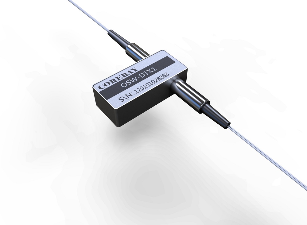
MEMS -1×N Optical Switch

Scope of application
Multi-channel optical monitoring in optical transmission system;
LAN multi-light source/detector automatic switching, optical sensing multi-point dynamic monitoring system;
In the optical test system, it is used for optical fiber, optical device, optical network and field engineering optical cable test;
Optical device adjustment.
Features
Fast switching speed and long life
Low loss, high reliability
Modular design, small size
TTL interface, easy to control
Technical indicators
| serial number | parameter | unit | index | Remark |
| 1 | Working wavelength | nm | 1250~1700 | |
| 2 | Test wavelength | nm | 1310&1550 | customizable |
| 3 | Fiber Type | single/multimode | ||
| 4 | aisle | 32 | 2-32 channels can be customized | |
| 5 | Insertion loss | dB | ≤1.0 | |
| 6 | return loss | dB | ≥50 | |
| 7 | repeatability | dB | ≤±0.02 | |
| 8 | crosstalk | dB | ≤-50 | |
| 9 | switching time | ms | ≤15 | |
| 10 | switch life | Second-rate | ≥109 | |
| 11 | Maximum input optical power | mW | 500 | |
| 12 | Operating temperature | ℃ | -5~+75 | |
| 13 | storage temperature | ℃ | -40~+85℃ | |
| 14 | Power Requirements | V | DC 5V |
Electrical Characteristics
1×N MEMS Optical Switch Electrical Characteristics Table
| serial number | parameter | unit | minimum | typical | maximum |
| 1 | Supply voltage (VCC) | VDC | 4.5 | 5 | 5.5 |
| 2 | Digital I/O logic high level (VIH, VOH) | VDC | 2.0 | 3.3 | 3.8 |
| 3 | Digital I/O logic low level (VIL, VOL) | VDC | 0 | 0.5 | 0.8 |
| 4 | Power consumption (@5.0V) | mW | - | - | 600 |
Instructions for use
Outline Drawing and Installation Instructions
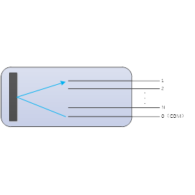
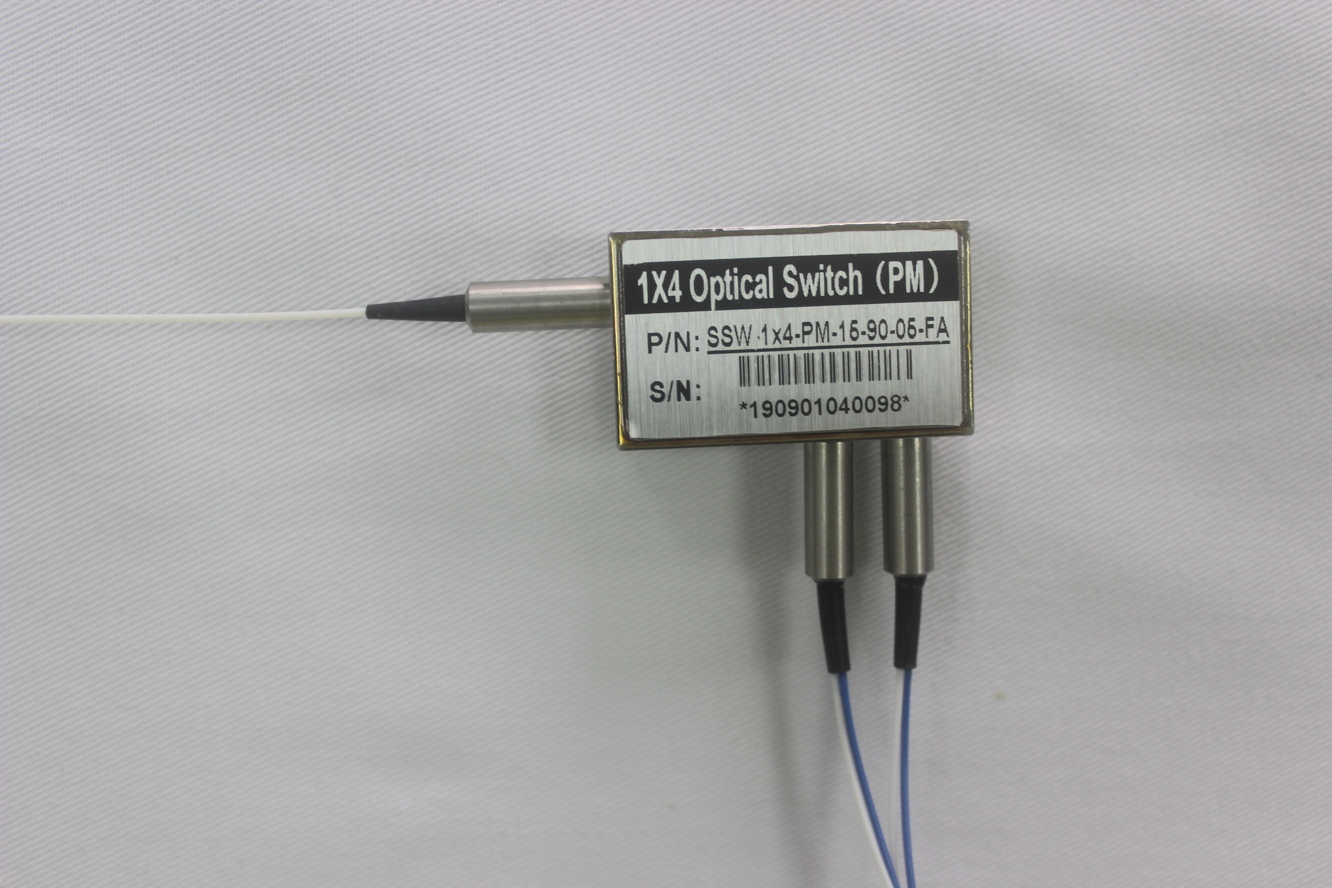
The external dimension of the MEMS optical switch module is 68 mm×30 mm×13 mm. Taking a 1×4 optical switch as an example, the external dimensions are shown in Figure 2 (other models only differ in the number of fibers):

When installing the MEMS optical switch module, the optical fiber must not be bent excessively (refer to Figure 3), so as not to affect the performance index.

Pin Definition
| pin number | pin definition |
pin type | level | Function Description |
| 1 | NC | / | / | / |
| 2 | VCC | Power IN | / | DC +5V Positive input of power supply, maximum current 120mA |
| 3 | /STROBE | IN | LVTTL | TTL mode: valid on falling edge |
| 4 | GND | Power IN | power ground | |
| 5 | D0 | IN | LVTTL | TTL mode: data bit D0 input |
| 6 | NC | / | / | Reserved interface, no electrical connection |
| 7 | NC | / | / | Reserved interface, no electrical connection |
| 8 | NC | / | / | Reserved interface, no electrical connection |
| 9 | D2 | IN | LVTTL | TTL mode: data bit D2 input |
| 10 | D4 | IN | LVTTL | TTL mode: data bit D4 input |
| 11 | GND | Power IN | power ground | |
| 12 | D1 | IN | LVTTL | TTL mode: data bit D1 input |
| 13 | D3 | IN | LVTTL | TTL mode: data bit D2 input |
| 14 | /RESET | IN | LVTTL | Reset, active low, pulse width ≥ 0.5ms |
Note: LVTTL is 3.3V LVTTL; STROBE (pin 3)
Only used in TTL mode, D0~D4 can change the level when it is high, and a falling edge pulse will make the optical switch switch to the corresponding channel.
RESET (14 pins)
A falling edge pulse switches the optical switch to the reset state, and the optical path is channel 1.
Instructions
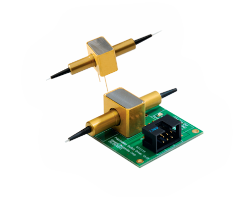
1) The MEMS optical switch module has a control circuit interface, which is connected to an external control circuit through a direct outlet. The interface pins are defined as shown in Table 3. After the optical switch is started, it is initialized to the reset state, and the optical path is channel 1.
2) After the optical switch module is powered off, the optical path cannot be maintained on the original channel.
3) The MEMS optical switch module has an input and output fiber bundle, and the fiber diameter is φ0.9mm. The input fiber (public fiber) is marked with 0, and the output fiber is marked with 1, 2, 3, and 4 respectively, indicating 4 corresponding output fibers.
4) MEMS optical switch module control mode: TTL parallel digital I/O control.
LVTTL parallel digital I/O control
LVTTL control can only be used for optical switches with 5 LVTTL control pins (D0, D1, D2, D3, D4), up to 32 channels. The corresponding relationship between the level of the LVTTL control pin and the channel is shown in Table 4. When using, the LVTTL control pin should be configured according to the actual number of optical paths of the optical switch.
| aisle | D4 | D3 | D2 | D1 | D0 |
| 1 | 0 | 0 | 0 | 0 | 0 |
| 2 | 0 | 0 | 0 | 0 | 1 |
| 3 | 0 | 0 | 0 | 1 | 0 |
| . . . |
. . . |
. . . |
. . . |
. . . |
. . . |
| 23 | 1 | 0 | 1 | 1 | 0 |
| 24 | 1 | 0 | 1 | 1 | 1 |
The logic control diagram is as follows

Precautions and maintenance
In order to avoid damage to the MEMS optical switch module, please read the following rules carefully before use:
1) Please use alcohol cotton to clean the fiber end face of the connector before use, and wear a dust cap when not in use to prevent dust or other dirt from contaminating or damaging the fiber end face. Damage or contamination of the fiber end face will affect the performance of the MEMS optical switch.
2) It is strictly forbidden to pull, fold or twist the optical fiber to avoid damage to the optical fiber.
3) For the detailed pin definitions of the control interface, refer to Table 3 above to ensure that the wiring is correct. After confirming that the connection is correct, power on again. Note: The working voltage of the MEMS optical switch module cannot exceed the rated voltage, and the power supply and ground cannot be reversed, otherwise the module will be damaged.
4) When the external circuit needs to be changed, please turn off the power first, and then disconnect the control line of the module.
5) When the MEMS optical switch module has optical signal input, do not look directly at the fiber end face. Laser radiation is invisible but can cause damage to the human eye!
6) This device should be fireproof and shockproof, and avoid storing and working in an excessively humid environment.
7) This device is a precision optical device and should not be disassembled without authorization to avoid damage.
8) The product is used under the specified conditions and will not pollute the atmosphere, water and land. The packaging does not contain hazardous waste and can be safely disposed of by the user.
9) The parts and components replaced by product maintenance shall be brought back by the maintenance personnel of our unit for disposal according to regulations. When the product is discarded or scrapped, the user shall dispose of it in accordance with environmental protection regulations.
Quick Inquiry
Related Products
.jpg)
Recommend Read
-
MEMS VOA
Guangxi CORERAY Optical Communication Technology Co.,Ltd.is an enterprise specializing in the manufacture of passi
-
MEMS VOA
While the widely use of micro-electro-mechanical systems (EMES) in some other industries is nothing new, its adoption fo
-
MEMS VOA
MEMS optical switch is a micro-optical switch that made of the semiconductor material, which is generally used as movabl
-
MEMS VOA
What is MEMS? MEMS (micro electro mechanical system) refers to the micro devices or systems that can be manufactured i
-

MEMS VOA
Mechanical switches are similar to optical switches, but they have a much longer history. The key difference from the op
-
MEMS VOA
The working principle of mechanical optical switch is to redirect the optical signal by physically moving the optical
-
_页面_01.jpg)
MEMS VOA
光开关国家标准 optical switch 1×2 Optical Switch Mechanical Optical Switch standard - People's Republi
-
MEMS VOA
Solid-State Variable Fiber Optical Time Delay(SSOTD) The SSOTD Series Photonic Time Delay provides a variable time dela
-
MEMS VOA
Solid-State Fiber optic Switch is an all-solid-state switching device that does not require any mechanical parts. It ach


_页面_01.jpg)
