
TOP

PRODUCTS
 Home > Products


The SSOTD Series Photonic Time Delay provides a variable time delay over a long range up to the millisecond. This is accomplished by selectively routing optical signals through N fiber segments whose lengths increase successively by a power of 2. Since each switching element allows the signal to either connect or bypass a fiber segment, a delay T may be inserted, which can take any value (in increments of DT) up to the maximum value T. This is achieved using non-mechanical configuration and activated via an electrical control signal. Latching operation preserves the selected optical path after the drive signal has been removed. The solid-state configuration eliminates the need for mechanical movement and organic materials.
The device is designed to meet the most demanding switching requirements of ultrahigh reliability and fast response time.
Features
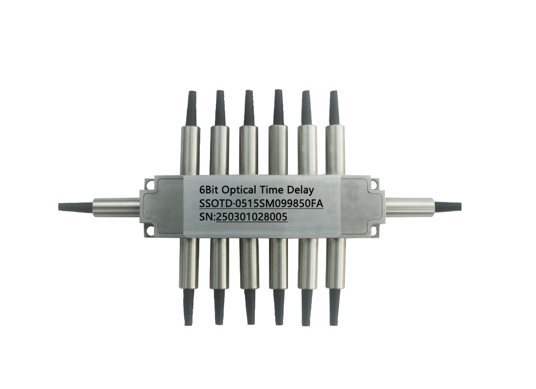
l 6-Bit Resolution or more
l High Speed
l Non-Mechanical
l High Reliability
l Fail-Safe Latching
l Low Insertion Loss
l Low Power Consumption
Applications
l Phase-Array Antennas
l Instrumentation
Specifications
Parameters | Unit | 6 Bit |
wavelength | nm | 1520~1580 or 1280~1340 |
Insertion Loss* | dB | Typ: 0.8 Max:1.5 |
Return Loss | dB | >55 |
Crosstalk | dB | >30 |
Switch Time | us | <150 |
Repetition Rate | KHz | 1 |
Switch Type | Latching | |
Polarization Dependent Loss | dB | 0.25 |
Fiber Segment Number | Loop | <8 |
Polarization Mode Dispersion | ps | 0.15 |
Polarization Extinction Ratio(PM Fiber) | dB | >22 |
Operation Temperature | ℃ | -5~+70 |
Storage Temperature | ℃ | -40~+85 |
Weight | g | 25 |
Dimension | mm | (L)68.4×(W)17.2×(H)9.5(±0.2) |
*:Loss of each group of bits
Electrical parameters
Parameters | Min. | Typical | Max. | Unit |
Switch Voltage | 4.8 | 5 | 5.5 | V |
Switch Current | 140 | 150 | 160 | mA |
Pulse Duration | 0.2 | 0.3 | 0.5 | ms |
Pins
Switch Position | Pin Group 1 | Pin Group 2 | Pin Group 3 | Pin Group 4 | Pin Group 5 | Pin Group 6 | Pin Group 7 | |||||||
Pin 1 | Pin 2 | Pin 3 | Pin 4 | Pin 5 | Pin 6 | Pin 7 | Pin 8 | Pin 9 | Pin 10 | Pin 11 | Pin 12 | Pin 13 | Pin 14 | |
Bypass | - | + | + | - | + | - | + | - | + | - | + | - | - | + |
1-bit | + | - | - | + | + | - | + | - | + | - | + | - | - | + |
2-bit | - | + | - | + | - | + | + | - | + | - | + | - | - | + |
3-bit | - | + | + | - | - | + | - | + | + | - | + | - | - | + |
4-bit | - | + | + | - | + | - | - | + | - | + | + | - | - | + |
5-bit | - | + | + | - | + | - | + | - | - | + | - | + | - | + |
6-bit | - | + | + | - | + | - | + | - | + | - | - | + | - | + |
Dimension (mm)

Ordering Information: SSOTD-A-B-C-D-E-F
A | B | C | D | E | F |
Mode | Wavelength | Fiber Type | Fiber Diameter | Fiber Length | Connector |
04:4-Bit 05:5-Bit 06:6-Bit 07:7-Bit 08:8-Bit | 13: 1310nm 15: 1550nm | SM09:SMF-28 PM13:PM1310 PM15:PM1550 | 25:250um 90:900um | 05:0.5m 10:1.0m 15:1.5m | OO:None FP: FC/PC FA: FC/APC SP: SC/PC SA: SC/APC LP: LC/PC LA: LC/APC |


Scan to add on WeChat


 中文
中文 EN
EN