
TOP

PRODUCTS
 Home > Products


Overview
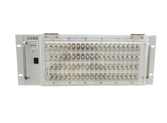
The optical switch utilizes a mechanical method to switch between input and output light paths for channel selection. It features small size, long lifespan, and stable reliability, and is widely used in optical network fields such as optical path protection and optical path channel switching. It has 4 built-in 1*16 optical switching modules, primarily implementing the function of inputting 4 groups of optical signals and selecting their paths. It has optical path switching and status reporting functions.
1. Specifications
Parameter | OSW-(4-1×16)-M6-85-4U-S22-LP |
Operating Wavelength (nm) | 850 |
Fiber Type | 62.5/125um |
Insertion Loss | <2.0dB |
Insertion Loss Consistency | <±0.25 dB |
Return Loss | <40 dB |
Channel Crosstalk | <40dB |
Repeatability | <±0.05 dB |
Service Life | >10^8 cycles |
Switching Time | <50 ms |
Operating Temperature | -20~+70℃ |
Storage Temperature | -40~+80℃ |
Operating Voltage | AC 110~260V |
Control Method | RJ45 Ethernet Port, RS-232 |
Connector | LC/PC |
Dimensions | 482.6×176×500mm (4U 19-inch Rack) |
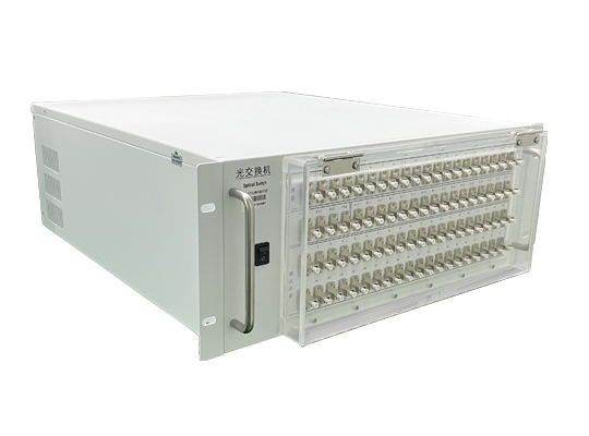
2. Dimensions (482.6×176×500mm (4U 19-inch Rack))

The chassis front panel houses the power switch, 21 LC/PC adapters, and an Ethernet port. The rear panel houses 21 LC/PC adapters and an AC power socket.
3. Precautions and Maintenance
3.1. Precautions
(1) When using this equipment, connect all ports correctly according to the optical path connection instructions.
(2) The power supply must be grounded, and the input voltage must be within the range required by this equipment.
(3) If sudden interference occurs and the host malfunctions, power it off first before handling.
(4) The optical input ports must be properly connected and accurately aligned; otherwise, measurement results and insertion loss may be incorrect.
(5) When switching optical paths, slight vibrations or sounds are normal phenomena.
3.2. Equipment Maintenance
Proper use and careful storage will maintain good performance indicators for a long time and extend the service life. Therefore, appropriate maintenance is required:
(1) Avoid strong mechanical vibration, collision, dropping, and other mechanical damage. During transportation, ensure good packaging with shock absorption, rainproof, and waterproof measures.
(2) Keep the equipment clean regularly. The working environment should be free of corrosive gases such as acid and alkali. Clean the chassis and panel gently with a clean towel dampened with water or soapy water. Do not use alcohol or other solvents for cleaning.
(3) Cover the dust cap immediately after disconnecting the fiber optic cable to prevent hard objects, dust, or other dirt from touching the fiber end face.
3.3 For matters not covered here, please contact us. We will be very happy to hear your valuable feedback.
4. Configuration List
No. | Item | Qty |
1 | Main Unit | 1 |
2 | Power Cord & Network Cable | 1 Set (Implied) |
3 | Certificate of Conformity | 1 |
4 | Test Report | 1 (Implied) |
5 | Manual | 1 |


Scan to add on WeChat


 中文
中文 EN
EN