
TOP

PRODUCTS
 Home > Products


n Product Description
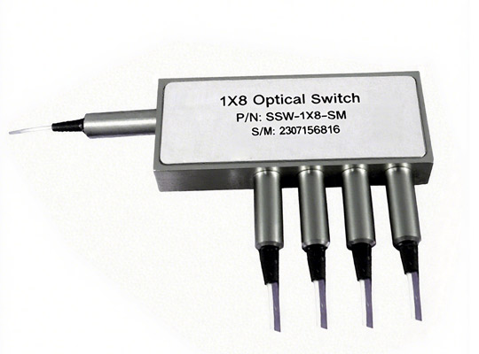
1x8 Solid-State Fiberoptic Switch connects optical channels by redirecting an incoming optical signal into a selected output fiber. This is achieved using patented non-mechanical configurations and activated via an electrical control signal. The latching operation preserves the selected optical path after removing the drive signal. The all solid state 1x8 Solid-State Fiberoptic Switch features low insertion loss, high extinction ratio, high channel isolation, and extremely high reliability and
repeatability. It is designed to meet the most demanding switching requirements of continuous operation without failure, longevity, operation under shock/vibration environment and large temperature variations, and fast response time. The switch also has build-in Circulator and isolator functions. An electronic driver is
available for this series of switches.
The magneto-optical crystals used in the CL switches have no fatigue nor drift effect.
n Applications
l Optical Signal Routing
l Network Protection
l Burst Switching
l Configurable Add/Drop
l Signal Monitoring
l Instrumentation
n Features
l High Speed
l Non-Mechanical
l High Reliability
l Fail-Safe Latching
l Low Insertion Loss
l Rugged
l Compact
l Cost Effective
l Direct Low Voltage Drive
n Performance Specifications
Parameter | Min | Typical | Max | Unit |
Operation Wavelength [1] | 1520 | 1550 | 1580 | nm |
1295 | 1310 | 1325 | nm | |
nsertion Loss [2] | 1.2 | 2.2 | dB | |
Cross Talk[2] Bidirectional | 35 | 45 | dB | |
Cross Talk[2] Unidirectional | 40 | 50 | dB | |
Return Loss [2] | 50 | 55 | dB | |
PDL (Except PM Series Switch) | 0.15 | 0.35 | dB | |
Extinction Ratio (PM Series Switch only) | 18 | 25 | dB | |
Polarization Mode Dispersion (SMF Series only) | 0.2 | ps | ||
Optical Switching Speed (Rise, Fall) | 5 | 10 | μs | |
Repetition Rate | 200 | Hz | ||
Durability | 1015 | 次循环 | ||
Optical Power Handling | 200 | 300 | mW | |
Storage Temperature [4] | -5 | 70[4] | °C | |
Storage Temperature | -40 | 85 | °C | |
Fiber Type | SMF-28, Panda PM 或等效 | |||
Weight | 59 | g |
[1]. Agiltron can achieve same SPEC at L band
[2]. Measured without connectors
[3]. Continuous operation, for pulse operation call
[4]. The premium versions with the operating temperature larger than -5 ~ +70°C are available,
please see the ordering information
n Mechanical Dimensions (Unit: mm)

*Product dimensions may change without notice. This is sometimes required for non-standard specifications.
n Electrical Driving Information
Each switching point is actuated by applying a polarity voltage pulse through a pair of PINS, and latched after pulse removed.
Parameter | Unit | Minimum | Typical | Maximum |
Resistance (each Pin group) | Ω | 15 | 18 | 22 |
Switch Voltage | V | 2.25 | 2.5 | 2.75[1] |
Pulse Duration | ms | 0.2 | 0.3 | 0.5 |
Notes:
[1]. Over this value will damage the device.
1) Driving kit with USB or RS232 with WindowsTM GUI or TTL interfaces is available.
2) Driving table can be provided per request for the customers to design/build their
own driving circuit.
Bidirectional 1x8, or 8x1 Switch Electrical Driving Table

[1]. “+”: 2.25~2.75V Pulse, Topical is 2.5V pulse
Unidirectional 1x8, Switch Electrical Driving Table

[1]. “+”: 2.25~2.75V Pulse, Topical is 2.5V pulse
Unidirectional 8x1 Switch Electrical Driving Table

[1]. “+”: 2.25~2.75V Pulse, Topical is 2.5V pulse
Note:
The driving voltage value is transient voltage with a full load. The driver circuitry needs to provide sufficient current (~300mA) during the switching. Inside the switch core is an electromagnet with a residual magnetic field. The residual magnetic field will be established when an electrical current flows in one direction through the coil for a sufficiently long period. The residual magnetic field latches the switch state even without applying a voltage (the current flow stopped). Flowing a current in the opposite direction for a sufficient time changes the switch stage by establishing a reversal magnetic field. The coil is forgiving to the driver unless one burns it by applying a higher voltage or a current for too long (day). The switch can also be operated at high repetition rates of kHz, where the residual magnetic field may not be fully established.
n Typical Switching Response

n Typical Loss Change of 1x2 vs Switching Numbers

n Functional Diagram

n Ordering Information: SW-A-B-C-D-E-F-H
A | B | C | D | E | F | G | |
Type | Wavelength | Switch | Package | Fiber Type | Fiber Length | Connector | |
18=1x8 81=8x1 17=1 x 7 71=7 x 1 16=1 x 6 61=6 x 1 15=1 x 5 51=5 x 1 00= Special | 3=1310 5=1550 0= Special | 2= Dual Stage | 2= Standard A=-40~+85°C B=-40~+70°C C=-20~+85°C D=-20~+70°C 0= Special | 1=SMF-28 B=PM 1550 0= Special | 3=900µm loose tube 1= Bare fiber 0= Special | 1=0.25m 2=0.5m 3=1.0m 0= Special | 1=无 2=FC/PC 3=FC/APC 4=SC/PC 5=SC/APC 6=ST/PC 7=LC/PC 8= Duplex LC/PC A=LC/APC U=LC/UPC 0= Special |
Example Model:SW-18-3-2-2-1-1-2
Description: Type: 1x8, Wavelength: 1310, Switch: Dual Stage, Package: Standard, Fiber Type: SMF-28, Fiber Length: 0.25m, Connector: None .
For custom components, please provide detailed requirements.
Fiber Core Alignment
Note that the minimum attenuation for these devices depends on excellent core-to-core alignment when the connectors are mated.
This is crucial for shorter wavelengths with smaller fiber core diameters that can increase the loss of many decibels above the specification if they are not perfectly aligned. Different vendors' connectors may not mate well with each other, especially for angled APC.
Fiber Cleanliness
Fibers with smaller core diameters (<5 μm) must be kept extremely clean, contamination at fiber-fiber interfaces, combined with the high optical power density, can lead to significant optical damage. This type of damage usually requires re-polishing or replacement of the connector.
Maximum Optical Input Power
Due to their small fiber core diameters for short wavelength and high photon energies, the damage thresholds for device is substantially reduced than the common 1550nm fiber. To avoid damage to the exposed fiber end faces and internal components, the optical input power should never exceed 20 mW for wavelengths shorter 650nm. We produce a special version to increase the how handling by expanding the core side at the fiber ends.LC
n Driver Design Example for 1x4
A recommended +5VDC powered driving circuit is provided. The resistor network R1~R8 is to suppress the driving signal’s voltage level to meet the “switch voltage” requirements. In specific applications, users can use lower voltage to eliminate the R1~R8. The Q1~Q8 is the control signal from either a function generator or a microcontroller general purpose I/O. The Q1-Q8 switching speedmust meet the specific MOSFET switching requirement and CL 1x4 Switch specific requirement. Usually, the control signal speedis ≤ 2kHz.


Scan to add on WeChat


 中文
中文 EN
EN